
The Extended ADSR creates the familiar 4- and 5-stage envelopes found on many synthesizers, and can also be patch-programmed to create complex envelopes.
While it's possible to use both sections of the Dual Universal Slope Generator (DSG) to create 4-stage envelopes, the Extended ADSR handles this natively while also providing a fifth stage (Delay) that precedes the Attack stage. This can be useful for delaying the onset of the envelope's Attack, especially when daisy-chaining multiple envelope generators or controlling multiple envelope generators from the same trigger or gate source.
All five stages are voltage controllable via unattenuated VC inputs. Adding voltage to these inputs is like turning the associated knob clockwise, lengthening the response time for the associated stage; subtracting voltage does the opposite. A master input (VC ALL) affects all of the envelope stages.
A 3-position switch at the bottom of the ADSR provides preset slope types for Attack, Decay and Release.
The ADSR includes separate inputs for gates and triggers, and responds differently to each. Both inputs can be used simultaneously to create complex envelopes.
The Extended ADSR can be made to self-cycle using a CV utility module, such as a Comparator or Schmitt Trigger, between the OUT and GATE / TRIG jacks.
The VC Inputs

Each VC input has a graphic next to it showing the portion of the envelope that's affected by that jack and its associated knob. These are hard to see in the function block graphic at the top of this page, so here are some close-ups.
The VC inputs have an exponential response, where most of the action is discernible with the knob set to noon or higher. Settings below noon are more subtle.
The AR Switch

The 3-position switch is handy for defining the type of slope behavior you want the envelopes to have.
TOP - Logarithmic Attack, linear Decay and Release
MIDDLE - Logarithmic Attack, exponential Decay* and Release
BOTTOM - Linear Attack, Decay and Release
* Note: The graphic for the MIDDLE slope shows a linear Decay, but it's actually exponential.
The GATE Input
The ADSR responds to signals at the GATE input in the typical way: when an input gate signal goes high the Attack stage is started (unless the initial Delay is something other than zero) and increases in voltage for the duration set by its knob. If the input gate is still high (or at least +4.5V) at the end of the Attack stage, the Decay stage starts and the voltage falls at a rate set by its knob down to the level set by the Sustain knob. The voltage remains at the Sustain level until the input gate goes low (or drops below +2.5V). When that happens, the Release stage starts and the voltage falls back to 0V at a rate set by the Release knob, after which the ADSR will wait for the next incoming gate signal.
Here are some scope images demonstrating the three switch positions above. The incoming gate signal is provided by a slowly cycling DTG whose blue output (fast Rise/slow Fall) is plugged into the ADSR's GATE input.


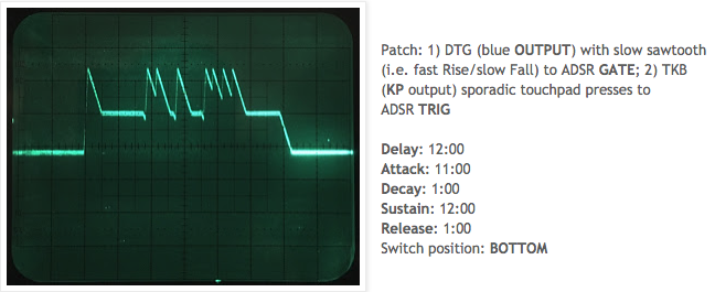
The TRIG Input
As mentioned above, the TRIG input behaves differently than GATE. How? Starting with similar settings as above, and moving the DTG > ADSR cable from the GATE input to TRIG, let's take a look:


So far these look like basic AD-type envelopes. Surely there's more to the story....
The TRIG Input Can be Totally RAD
When using the TRIG input, the Sustain knob acts like a DC offset. If you increase the Sustain level to the midpoint, the envelopes can go down as well as up. But why then did they not do so in the previous images?
If the Delay amount is increased, something interesting happens:


Here's how it works:
With nothing inserted at GATE, the starting voltage is determined by the Sustain level. When a trigger is received at TRIG, the voltage drops toward zero at a rate set by Release, but subject to the Delay time. Once the Delay time has completed, the voltage rises at a rate set by Attack, and then drops back to the original Sustain level at a rate set by Decay. So we end up with RAD or RDAD envelopes (though it still looks like a 0V to +5V ADSR envelope).
A simple demonstration should help illustrate this. In the series of photos below, the only change is to the Delay time, which is set to 9 o'clock to start. All of the other knobs are at noon. For each trigger, the Delay time is manually advanced up one "hour" until the maximum duration (5:00).


Another way this can be seen is to instead change the Release time with each pulse, and leave the Delay time at noon. In the next series of photos, the Release time starts at noon and is reduced by one "hour" per pulse.


The initial drop that signals the envelope start gets larger with each pulse, which might make you think the counter-clockwise rotation is having some sort of inverse response (we're used to "bigger" equating to "more"). But remember, the trigger causes the voltage to drop from the Sustain level to 0V, subject to the Delay time, which has remained unchanged. So the Release stage has the same amount of time to reach 0V with each pulse. The less time it spends slowing its descent, the more vertical distance it will travel.
Using GATE and TRIG Simultaneously
When GATE and TRIG are used at the same time, GATE takes precedence for the Delay, Attack, and Release stages — triggers that occur during those stages are ignored. Triggers received during the Decay and Sustain stages will interject cycles of their own for as long as the input gate is high.
As soon as the input gate goes low, the GATE Release stage will take over from wherever the envelope's voltage is at that moment. If that happens to be a higher voltage than the Sustain level, the Release stage may not have time to complete (since it has further to travel), in which case the next input gate signal will start the GATE DADSR cycle from wherever the voltage level happens to be. This allows for the creation of interesting and complex envelopes.
Here are some examples using both inputs at the same time:


The VC All Input
The original Serge catalogs had this to say about the VC ALL input:
"A master 1V/OCT control will control all slope times to allow such effects as decreasing the entire envelope time as the pitch of an associated oscillator increases."
Though not explicitly stated, this meant that the VC ALL input inverted the incoming signal so that an increase in voltage (e.g. associated with an increase in pitch) shortened the durations of the stages — which, depending on one's preferences, could be great... or not!
Extended ADSRs produced in later years may or may not be configured this way. Mine isn't. In the event that I want the envelopes to track with my keyboard, it merely requires inserting an inverter, like the Active Processor (ACPR), between the keyboard's pitch CV and the VC ALL input.
Whichever way your ADSR is configured, and however you have to get there, this feature is really cool, because as the catalog states: "This phenomenon is typical of many acoustic instrument envelopes."
Here's an example using an external keyboard to play a series of pitches starting at the lowest key on the keyboard, and progressing up through higher and higher pitches. In the image below, the envelope time shortens as the pitch goes up.

Self-Cycling
The ADSR can be made to self-cycle using its GATE input (generally yielding AD envelopes) or its TRIG input (yielding more complex envelopes). With either input, the Delay stage controls the cycling rate, which can be one envelope cycle every 3-4 seconds (fully clockwise) to well into the audio range (fully CCW).
Most slope generators in the Serge family (e.g. DSG, DTG, TGO, etc.) have a separate gate output that sends a pulse at the end of the Rise/Fall cycle. Sending this pulse back into the module's own input causes the Rise/Fall cycle to begin again. The ADSR, on the other hand, doesn't have a separate output for this purpose, so it doesn't natively have a way to kick start the next cycle on its own. It needs a helping hand.
And speaking of helping hands: I want to give a shout-out to cebec for his initial testing and for showing me how to get the ADSR to self-cycle. Thanks, my friend!
Let's take a moment to explore some helpful utility modules, as it will lead us into exploring different self-cycling behaviors of the ADSR.
A couple common CV processing tools that can aid this purpose include the Comparator (COM) and the Schmitt Trigger (STR). The COM and STR perform the same function, which is to compare an incoming signal against a predefined voltage threshold, and change state if that threshold is crossed. In this case, we want to send a gate signal back to the ADSR when the envelope ends. In voltage terms, that means when the envelope ends, the voltage goes low. We need something in the signal path to observe that event and send a gate (high) signal when it occurs — and these two modules excel at that task.
The ÷N Comparator (NCOM) works great for this too — in fact, the NCOM's lower portion is the same as that found in the Dual Comparator. The NCOM's upper OUT÷ can also be used, and actually performs a cool trick: Feed an audio rate cycle from ADSR OUT to NCOM IN-, and NCOM OUT÷ to ADSR GATE (or TRIG). Start with NCOM's divider knob fully counter-clockwise. Once the ADSR is cycling, turn the NCOM divider knob to about 9 o'clock, and watch the ADSR's cycling verrrry slowly grind to a halt. If you catch it before it does (with voltage control, I wonder...?), and set the divider back to fully CCW, you can repeat the process.
To a limited extent, the lower portion of the Active Processor (ACPR) can also be used. It seems like it should work just like a COM, but it actually behaves more like an envelope follower with just enough rise to keep the ADSR cycling with the GATE input. In my tests, the TRIG input doesn't respond to the ACPR, probably because, like other Serge modules with a TRIG input, they expect to see a very fast Rise in order to trigger.
OK, now that we've identified a few tools available to us, how well do they work?
First, be aware that when you first connect the utility module inline with the self-cycling patch, the ADSR may not start up on its own. In that case, swing the knob on the COM or STR back to zero (noon) and then quickly back to about 3:00. That'll generate a gate that will then get the ADSR cycling. This works whether you're using the GATE or TRIG input.
Suggested starting ADSR stage positions (using the COM or STR) are as follows:
When using the GATE input:
Delay: 3:00
Attack: 12:00
Decay: (ignored)
Sustain: (ignored)
Release: 12:00
When using the TRIG input:
Delay: 3:00
Attack: 12:00
Decay: 2:00
Sustain: (ignored to 2:00, above which the cycling will stop)
Release: 12:00


Notice in the images above that the leading edge of the gate (upper trace) lines up with the peak of the Attack (lower trace). Compare that with the following image of a self-cycling DTG, where the leading edge of the gate clearly lines up with the beginning of the Attack.

The only conclusion I can draw from this is that when self-cycling using the GATE input, the ADSR has a delayed response to the incoming gates. Why the same can't be said for the TRIG input (see the next image), I can't say. In any case, it works!
How about the TRIG input? Depending on the granularity you're after, it's potentially more useful than the GATE input since you can get all of the envelope stages involved (except for Delay, which, as mentioned earlier, becomes the rate control), yielding more complex envelopes. And since we peeled apart the TRIG input's behavior, you won't be surprised when your RAD cycling envelopes start with the Release stage.

Further Further Further
There are more possibilities to explore with self-patching, daisy-chaining ADSRs, cross-patching ADSRs, inserting complex voltage sources at the VC inputs... perhaps for a future post. Until then, I hope that you have a better handle on this surprisingly versatile extended envelope generator. I know I do now!
No comments:
Post a Comment